
Last edited: 8.12.2023
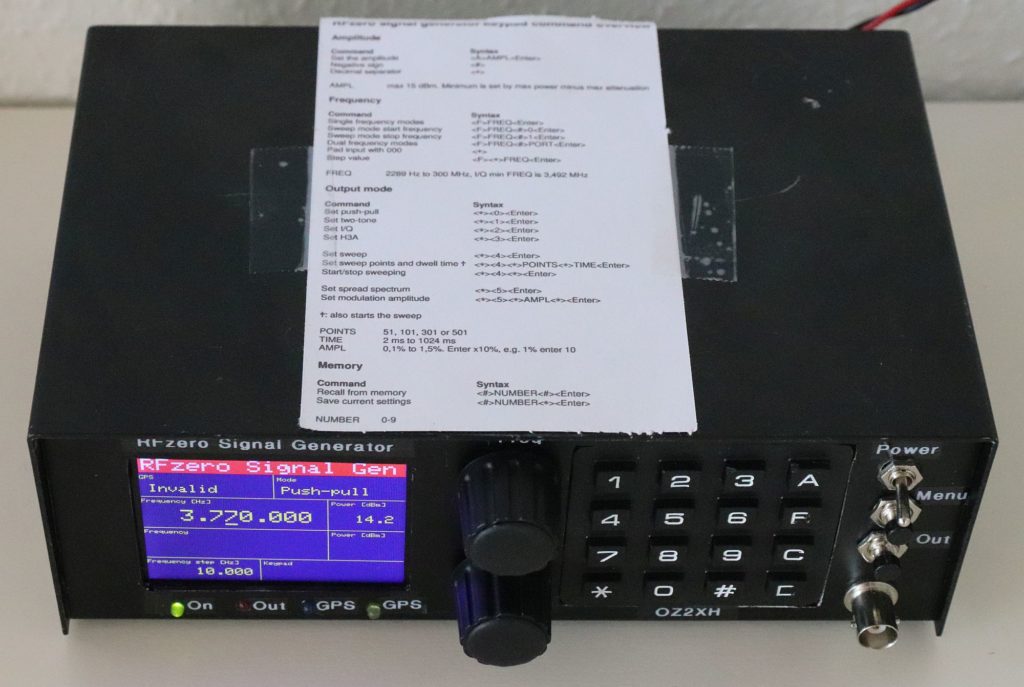
Here my solution to the RFzero Signal Generator:
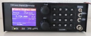
I decided for the graphical TFT display, two encoders (for frequency and attenuation) and a keypad.
I used a housing I had in stock, it is a little small so I had to shrink everything.
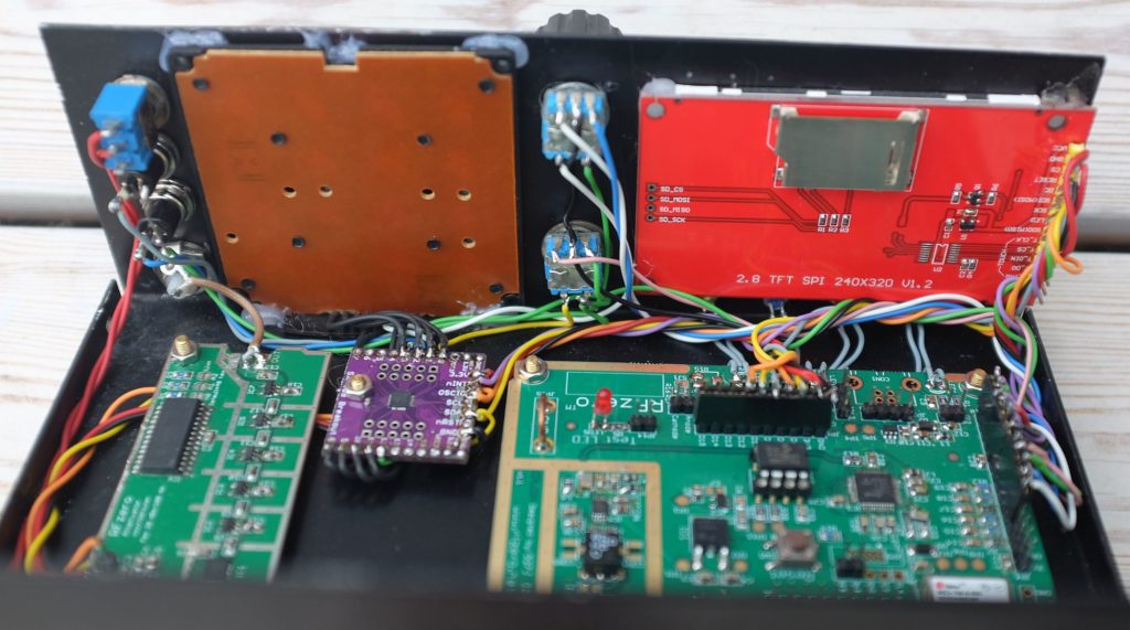
So I had to remove all SMA connectors and connect by soldering shielded wire directly to the PCBs.
The components in my generator are:
Display: 2.8″ TFT SPI 240×320 (eBay)
Supply: 8-20V DC (13V 0.06A) with step down converter to 5V (eBay)
Encoder: top is for frequency, bottom is for attenuation
Expander: SX1509 (eBay)
Attenuator: RFzero I2C in mode 7 (11 bits, 0-106,5 dB in 0,5 dB steps). Please note, this is a RFzero prototype and will not be available for sale because of bad performance at high attenuation. We have a 76 dB version in progress, maybe that will be available at a later time.
Case: I used a aluminium box. It is 200 mm wide, 70 mm high and 130 mm deep.
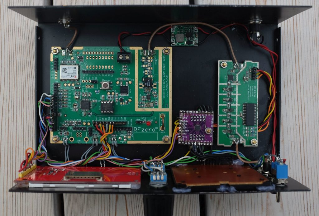
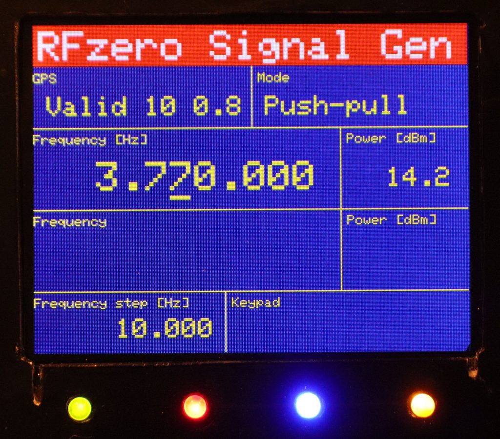
LEDs:
Green – Power ON
Red – Output on
Blue – GPS impulse
Yellow – GPS Ready
Here a shortform of the command syntax, very hard for me to remember :-).
Here the schematic in pdf of the external connections to the display, attenuator, SX1509, encoders, keys and keypad: SigGen_oz2xh_200924