QO100 setup
My new QO-100 setup with a RFzero GPS stabilized generator and a transverter made by Steen OZ5N.
The RFzero is running with the QO-100 SW.
It can generate two independent frequencies, both GPS locked.
- One signal is a 25 MHz reference signal for stabilizing the LNB.
- The second is a lo inject for mixing down the IF frequency (nominal 739 MHz) from the LNB to the 70 MHz in my radio. The same signal is used for upconverting the TX signal.
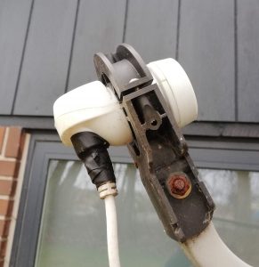
The LNB is a cheap item from a Danish ware house Harald-Nyborg (59 Dkr), it is a Maximum ST-11 #5650.
Unfortunately it is not available any more.
I have modified mine for external reference frequency (25 MHz).
You can read how to do this here, this page is made by OZ2OE and is in Danish.
Here a description of a two port LNB modification and how he runs it with a RFzero, made by OZ1BXM.
The design of the needed frequencies is made by OZ5N.
His transverter can be adjusted to use at lot of IF frequencies.
I prefer to run it on 70 MHz on my Icom IC-7300.
The idea is to have two fixed GPS locked frequencies, one for the LNB and one for the transverter action.
The RFzero QO100 SW is capable of switching one of the frequencies between RX and TX, but this is not needed here, the two frequencies are chosen so the RX and TX use the same inject frequency
Here you can read the needed frequencies for different output/input combinations:
| Option | fTX [MHz] 21 - 125 | fRX [MHz] 1 - 146 | f0 [Hz] | f1rx [Hz] | LNBif [Hz] |
|---|---|---|---|---|---|
| 1 | 50.5 | 50.5 | 24,758,547.009 | 261,055,555.556 | 833,666,667 |
| 2 | 70 | 70 | 24,725,213.675 | 258,888,888.889 | 846,666,667 |
| 3 | 50 | 50 | 24,759,401.709 | 261,111,111.111 | 833,333,333 |
| 4 | 70 | 50 | 24,776,495.726 | 258,888,888.889 | 826,666,667 |
| 5 | 50 | 70 | 24,708,119.658 | 261,111,111.111 | 853,333,333 |
| 6 | 70.5 | 70.5 | 24,724,358.974 | 258,833,333.333 | 847,000,000 |
| 7 | 49.5 | 49.5 | 24,760,256.410 | 261,166,666.667 | 833,000,000 |
| 8 | 69.5 | 69.5 | 24,726,068.376 | 258,944,444.444 | 846,333,333 |
| 9 | 89.5 | 89.5 | 24,691,880.342 | 256,722,222.222 | 859,666,667 |
| 10 | 21 | 29.5 | 24,787,179.487 | 264,333,333.333 | 822,500,000 |
| 11 | 50 | 2 | 24,882,478.632 | 261,111,111.111 | 785,333,333 |
| 12 | 21 | 50 | 24,734,615.385 | 264,333,333.333 | 843,000,000 |
I use option 2.
LNBIF is 10.498.500.000 -(f0 * 390) = 846.666.667 Hz. (390 is multiplication factor in the LNB).
fRX is made by multiplying the f1RX * 3 and subtracting from the LNBIF: 846.666.667 – 258.888.889 * 3 = 70 MHz.
fTX is Output – f1RX * 9 = 2.400.000.000 – 258.888.889 * 9 = 70 MHz.
So when my radio is showing 70.200 MHz, I am receiving 10.489,700 MHz and transmitting on 2.400,200 MHz.
Antenna
For receiving I use an old 85 cm TRIAX, from the days when we received TV via parabolic antenna.
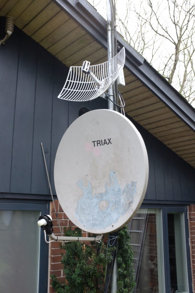
Now I added the TX antenna which is a 2.4 GHz antenna from a wireless Internet installation. I should have a gain of 18 dB.
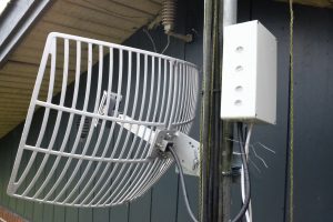
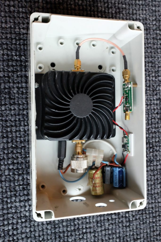
The box contains a driver (ADL5324) and cheap Chinese WiFi PA stage (8W). The cable from my shag to the TX box is cheap 75 ohm TV cable with F connectors.
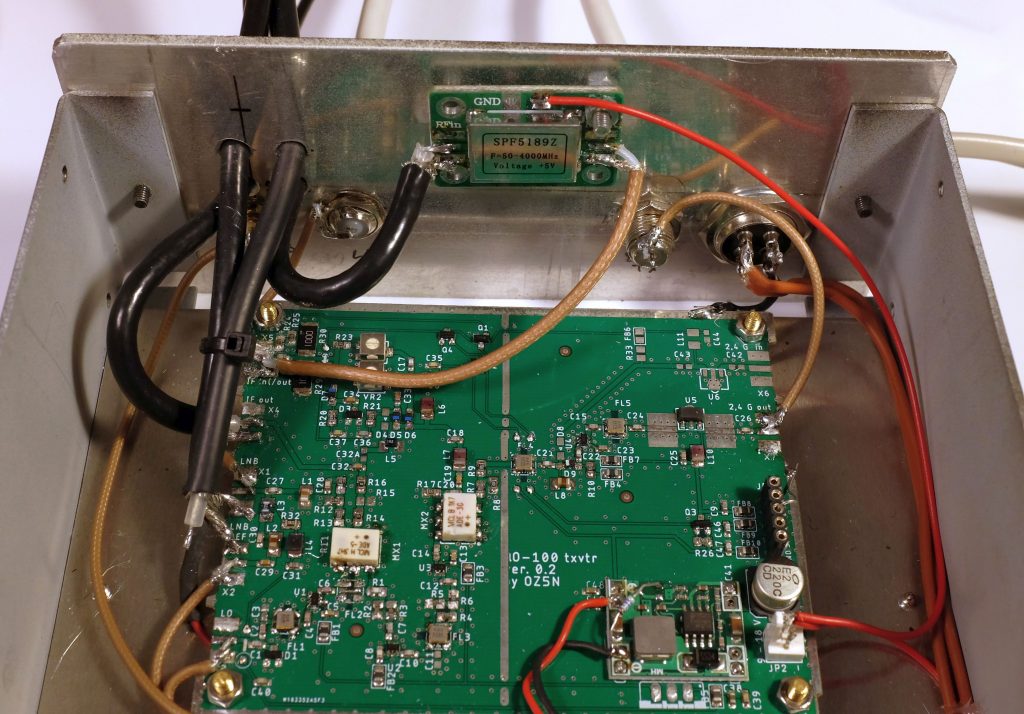
Transverter
My homemade transverter for the QO-100 satellite.
Not finished the TX part yet on the picture.
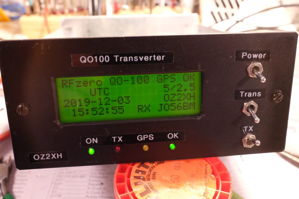
- Power: Switch for power (12V).
- Trans: Switch for activating the transverter interface in the Icom IC-7300
- TX: Switch for switching the power for the TX
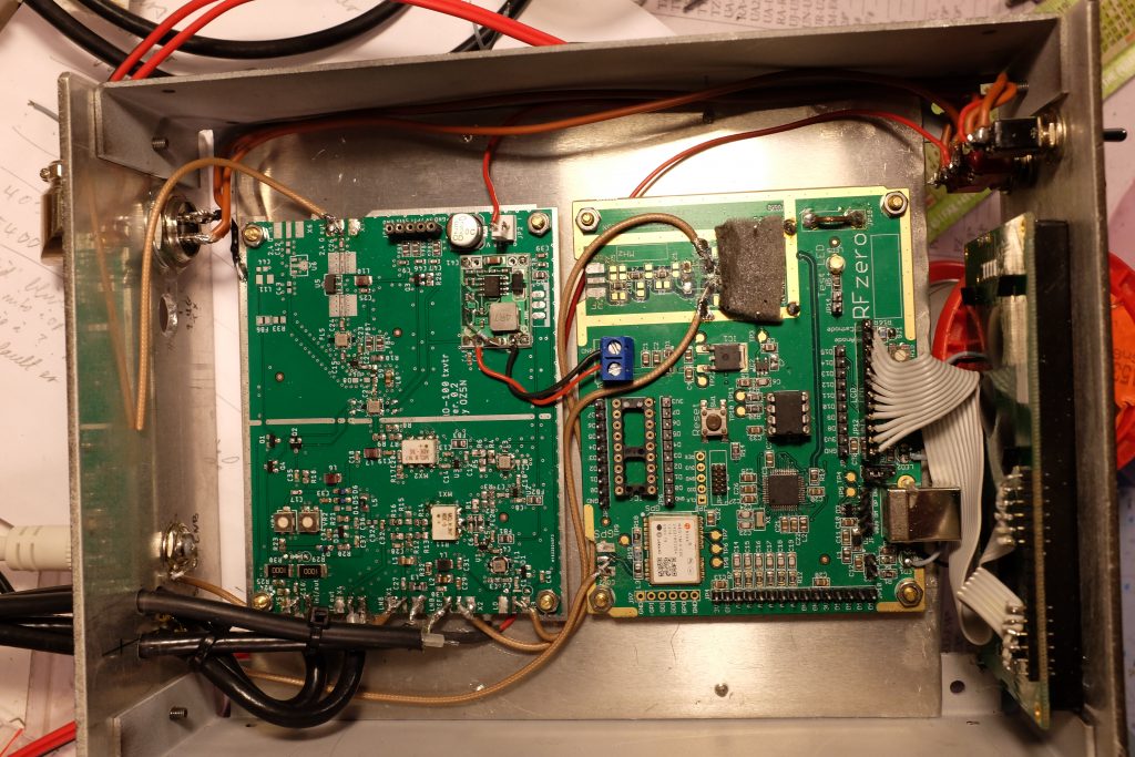
The two circuit boards. TX not finished yet.
The transverter board (to the left) is a prototype V0.2 made by Steen, OZ5N.
It is unfortunately not available for sale, it is not come to a production phase only some prototypes exist.
Here the schematic of the transverter. QO100 transverter0_2_sch
The PCB to the right is the RFzero V1.0.
The output from my transverter interface was very low (8uW) so I had to add an amplifier to the 70 MHz signal. This is a cheap China board with a SPF5189Z
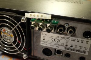
Kuhne DB6NT transverter interface in place in my IC-7300.
When I switch on the transverter a DC output is activating the interface and RX and TX signal goes to the transverter.
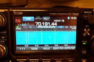
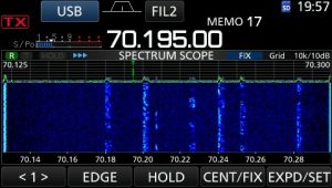
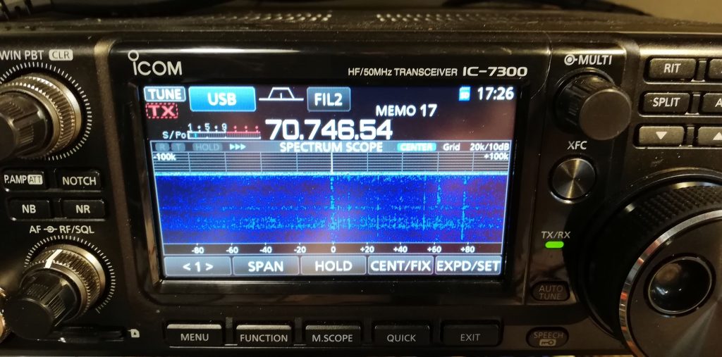
Nice output on my Icom IC-7300.
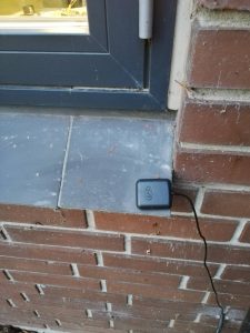
GPS antenna
I had to put the antenna outdoor so the GPS can get reasonable signal and short time to first fix (about ½ minute).
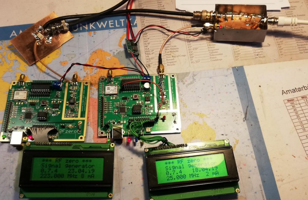
Spring 2019
This was my first approach to listening to the QO-100 satellite.
I used two RFzero and made a mixer (ADE-1) and a diplexer (OZ2OE), so I could listen on my Icom IC-7300 on 70 MHz.
Antenna is a 85 cm Triax dish.
One RFzero generated 25 MHz for the reference signal to the LNB.
The other with 223 MHz signal for down converter from 739 (LNB) to 70 MHz (739 MHz – 3 x 223 MHz = 70 MHz).
This was before the RFzero had SW (QO100) to generate 2 simultaneous frequencies.